At Tweede Golf we've helped multiple clients develop hardware abstraction layers (HALs) for the chips they're using. A big aspect of that is verifying that the code we wrote actually works. But this is tedious and hard to do right. So we've been working on making it easier.
At Tweede Golf we've helped multiple clients develop hardware abstraction layers (HALs) for the chips they're using. A big aspect of that is verifying that the code we wrote actually works. But this is tedious and hard to do right. So we've been working on making it easier.
The trouble with ad-hoc testing, an anecdote
When adding support for a UART, it means hooking up the development board to some serial port to see if we can send and receive bytes. However, this is not sufficient most of the time. If we left it at that, we would only test the happy path, and even that only roughly.
For example, in one HAL we worked on, we ended up with a slightly erroneous baud rate calculation. Everything would work as long as we only sent 8-bit words with no parity. Adding parity would spuriously cause errors to show up. It took a while to check that the hardware was hooked up correctly, and eventually we connected a logic analyzer to check what was going on on the actual wire. The timing turned out to be off by so little that, for shorter transmission, everything lined up just right; however, for longer ones, the clock rates would drift apart too far.
Another issue with these ad-hoc test setups is testing error cases. For parity testing, you can play with the config to force, for example, incompatible parity bits, but it takes quite a bit of time to set something up that works wrong on purpose.
Furthermore, these test setups are not really transferable between projects. The wiring will be different, your USB to UART converter changes, and even what targets there are to test with will differ between boards. Some might have an I2C EEPROM to test with, others an I2C temperature sensor.
Making it reusable
So we wanted to have a reusable set of tests that we can take from project to project.
Conformance test suites like this are nothing new for pure software projects. For example, there is the sort-research-rs repository, which has a set of tests to check if a generic sorting implementation is correct, even for cornercases like panicking comparison functions. For HTTP/2, there is the h2spec conformance testing tool.
These tests allow implementations to learn from each other. If you start out writing a sorting function, you don't have to know of all cornercases beforehand, because the test suite will tell you if you missed something. Also, if you discover a new cornercase, you can contribute it back the test suite, meaning all implementations will now also be tested on this new cornercase. This empowers more people to enter a domain where otherwise years of experience are needed.
The resulting code is open source and can be found on the embedded-conformity repo on GitHub. Below, we'll delve into the design process.
Hardware Setup
Adding hardware into the loop for these test suites might sound challenging. How would you write an assert_eq!(data_sent, [0,1,2]) after all, like we do in software tests? Luckily, we can actually make it quite similar to the software tests so we can still call a function to see if the reaction is what we expect. We just need extra hardware to see what our actions caused to happen in the real world.
We "simply" add another microcontroller in the form of an Arduino Shield, using the standard Arduino pinout that can emulate all the common interfaces (like UART, I2C and SPI). Almost all dev-boards offer some way to connect an Arduino Shield, and for the others, we can make adapters.
Software setup
With this setup we can write tests that instruct the tester shield to behave a certain way, e.g. sending a stream of bytes over UART where one of them has the wrong parity bit state. With this approach, we've written test code that targets the embedded-io traits. We send bytes and validate that errors are returned for the received bytes with the incorrect parity, but not others. We just need a shim to connect the chip's HAL to the tests and bingo: we have reusable hardware-in-the-loop tests.
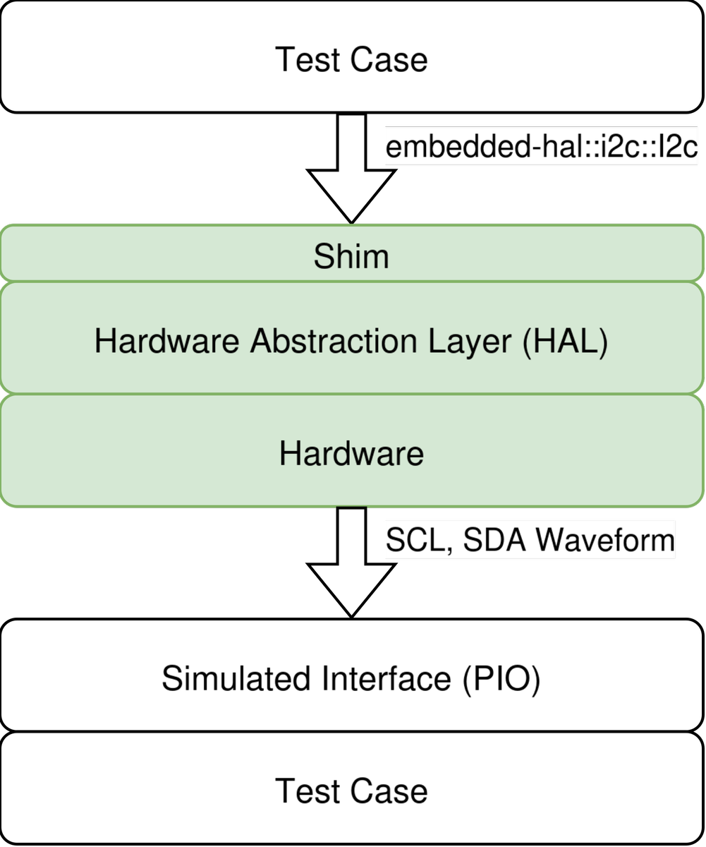
Image: the concept
One hurdle up to this point had been to find the time to develop the system. Luckily Vivian joined us to write her Master's thesis about developing a proof of concept of the idea. She targeted I2C, a notoriously complex protocol to implement correctly.
Plugging it all together
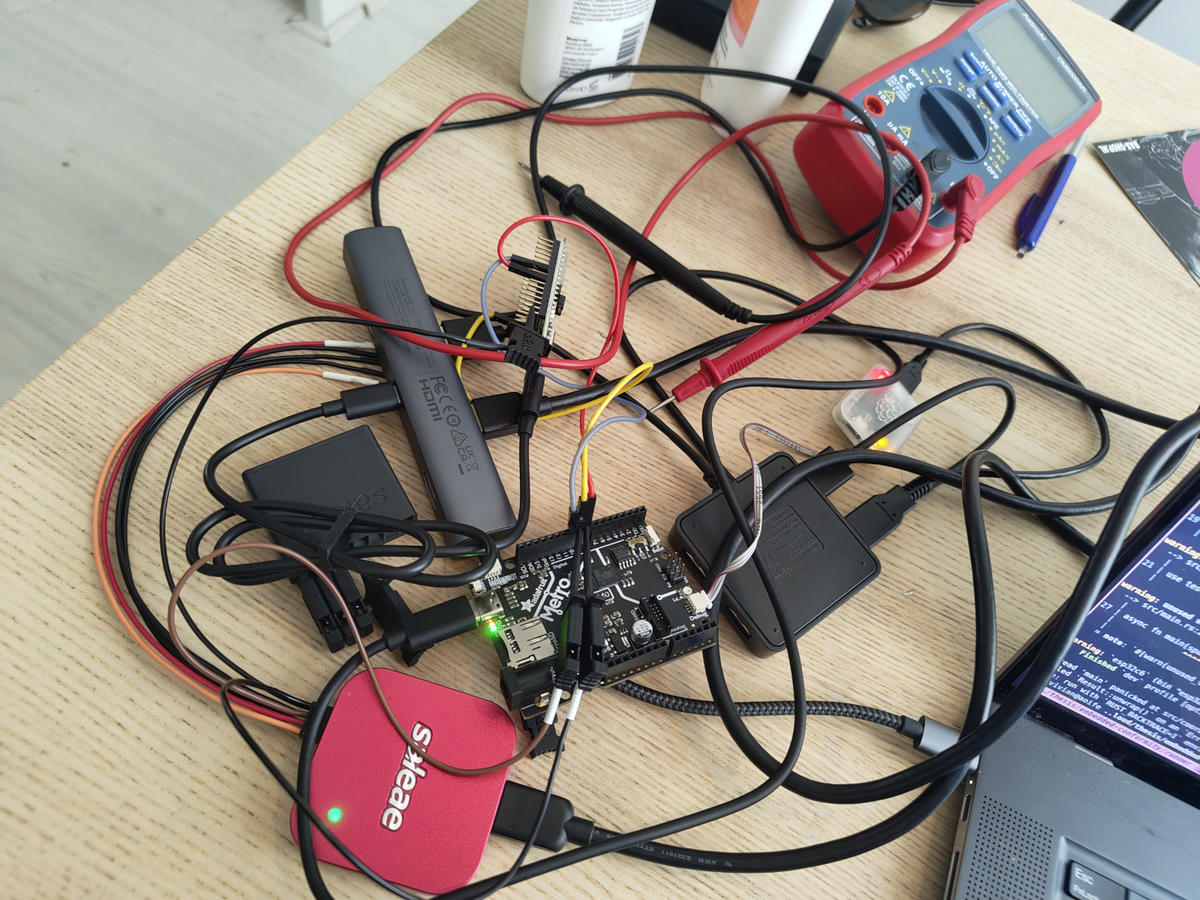
Image: A collection of PCBs with jumper and USB cables
Vivian started out by connecting an RP2040 with jumper wires to an nRF52 dev board we had lying around. The dev board's on-board debugger was hooked up to a USB Hub, along with a debugger for the RP2040 and the RP2040 dev board itself (for power). We then connected the I2C pins of the RP2040 to our nRF52 dev board. This gave us all the connections we needed - at the cost of some wire mess. This worked and only crashed the USB host controller if we also used a logic-analyzer at the same time - nice!
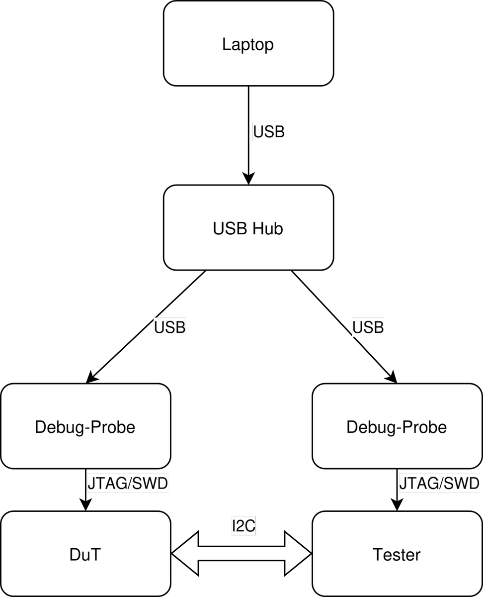
Image: a schematic view of the setup
If we ignore the physical clutter and just have a schematic view of the setup, we can see that our developer PC can now talk to both the device under test (DuT) and to our tester using debug probes.
Now we just have to build a firmware for both the DuT and our tester, flash them to the two boards and make sure to start the right test on both boards at the same time. This worked for a single test and a single board relatively nicely. Just open two terminals, run cargo run --release for the two boards and we're done! But of course that does not scale well, so we set about improving the setup.
Improving the software
First we added a third Rust project - all problems can be solved by another component, after all. This program runs cargo as a library to compile both firmwares, figures out where the binaries have been written to, and uses probe-rs to flash both boards with their respective firmware. It then uses RTT (Real-Time Transfer I/O protocol) to attach to both boards, to collect their defmt logs. We also use RTT to instruct the boards which test to execute, and collect the result of the test cases. This way we don't have to reflash the board for every test, but only once.
With this setup we get (mostly) synchronized logs via defmt, which we then print to the user using tracing. We also collect all test results and present them in a nice report.
Improving the timings
We started out using the I2C peripheral of the RP2040 to simulate an I2C device. And with it, we found a problem when testing against an ESP32-C6! The RP2040 was very slow to respond, so it stretched the clock for about 2 ms which is unusual, but allowed by the I2C spec. On the ESP side, however, it caused a timeout to trigger erroneously, which was the first issue that we discovered with our experiment.
Finding a problem like this is nice, but we weren't slow by choice! It's a consequence of using the I2C peripheral. Being limited by slow response times might hide other problems. There is a secret reason behind choosing the RP2040, though. It has a special peripheral called "Programmable I/O" (PIO) that allows us to emulate a lot of interfaces with precise timing.
We chose the PIO over something more powerful like an FPGA, since it is easier for most programmers to think about, cheaper and does not require special tooling.
Improving the hardware
We've been working on this project at many different locations and after carrying the prototype setup back and forth a few times, the wiring became increasingly annoying. So we designed a PCB using KiCAD that contained all the necessary wiring and even a USB hub.
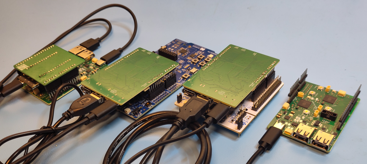
Image: Four stacks of PCBs
The shield houses two RP2354B microcontrollers. One handles the interface emulation (called tester) and the other is used as an on-board debugger. They are both connected via USB to the on-board USB hub - a CH334F. The other two ports of the hub are exposed as USB-A plugs to be able to easily connect the device under test. These two ports can also have their power measured with a shunt resistor and an INA219 and they can be turned on and off.
The GPIO pins of the tester are connected via 100 Ohm termination resistors to the Arduino Uno header. The analog pins also get an extra set of GPIO pins via a low-pass filter so we can create analog voltages using PWM. After some feedback we also added a USB mux, which allows one USB-A port to be connected to the tester MCU so we can use PIO to also emulate USB (at some point in the future).
So now all we need to do to use a board is plug in the shield and plug in the USB cable(s), then connect a single USB-C cable to our laptop and we are good to go.
What's next?
Our vision was and is to make Rust HAL developers as confident in their implementation as somebody implementing HTTP2 or a sorting algorithm. To make this a reality, we developed a PoC for a universal hardware-in-the-loop HAL test suite.
Now that we know that our idea is feasible, and provably works for a complex protocol like I2C, we want to move beyond a PoC to a more comprehensive solution, and we have a plan. Primarily, we want to:
- expand the test suite to cover all of the
embedded-hal(-async)andembedded-io(-async)traits; - expand how many HALs and hardware versions we test;
- make the user experience of running the test-suite better.
Check out the roadmap for the milestones and any other future work we'd like to do to turn this proof of concept into a common and robust tool.
We are looking for funding to continue this work, so if you have the opportunity to support it financially, we'd love to hear from you.
If you or your team have a need for testing your hardware, or you want to make it easier to write well tested HALs, please reach out to us as well; We would love to hear your feature requests.