Measuring power consumption: sync vs. async
Our expectation is that async allows us to be more energy-efficient in non-trivial applications for two reasons.
Firstly, async is more fine-grained in when to switch to another task. That means that on average work is completed earlier, and the system can go to sleep for longer. On mobile devices, "race to sleep" is an effective way to decrease power usage.
Secondly, async implicitly uses wait-for-interrupt (e.g. inside the I2C implementation) where the synchronous version uses busy-waiting. That means the path of least resistance (using the hal for sync, embassy for async) is more efficient for async.
The setup
We've been running our code on an nRF52840-DK, a hardware development platform designed by Nordic featuring the nRF52840. It contains all components necessary to start developing applications for this chip, such as RF machinery for Bluetooth applications, pin headers for easy attachment of external devices, and a SEGGER J-Link debugger. It also boasts various switches and connectors to control which parts of the DK are switched on, and where they draw power from.
When measuring the effect of async on power usage, we want to isolate the usage from the nRF52840 itself as much as possible. We're not interested in the power usage of the sensors (or the other components on their breakout boards for that matter), nor do we want our measurements to be influenced by the debugger. Fortunately, the DK gives us the control we need.
First of all, the board can be put in 'nRF only' operating mode. In this mode, the debugger and its LEDS are switched off. Even the signal lines are cut from the nRF52840. This mode is enabled by setting switch SW6 to 'nRF ONLY'. We are using the nRF only mode not only to rule out the debugger's power usage, but also to minimize any interference coming from it.
Furthermore, the DK supports enabling direct supply to the nRF52840. We can switch SW10, which is labeled 'VEXT -> nRF', on to enable direct supply. This way, we can power the nRF from a source distinct from whatever powers the rest of the board. The P21 pins on the board, labeled 'External supply', allow it to connect an external power source. When enabling direct supply, this power source powers only the nRF52840, while the rest of the board is powered via the USB cable. That means that when we measure the current the external power source supplies, we are measuring only the current that the nRF52840 uses. Which is exactly what we want to do. Now in order to measure the externally supplied current, we're using an Otii Arc Power analyzer. This device acts as a power supply, and allows us to very precisely see how much current is used over time. It even comes with a fancy plotting tool that visualizes the measurements over time for us. Very helpful. We're going to use the Otii Arc's numbers for our analysis.
What's left to do is hook up the sensor breakouts. We've hooked up the ground and signal wires of the sensors to the DK. However, the sensors, along with their status LEDs and other circuitry, are powered by yet another external power source, as another measure to isolate the power usage.
Before we begin collecting data, we have to note that the power usage of the nRF52840 is greatly influenced by the number of peripherals that are enabled. This is pointed out in section 5.1. of the product specification. The chip's Power Management Unit or PMU detects which subsystems are in use and need power, and which can be cut off. As such, we cannot simply compare the raw numbers we get from each and every test case. But the raw numbers are not that useful anyway: we test on the development kit of one particular model with a particular CPU: the numbers would never translate directly to any other piece of hardware. Nonetheless we believe that the relative differences will map to other hardware.
The baseline
As a baseline, we're interested in power consumption while the system is idle. Based on the specification we should observe power consumption in the micro-ampére range (µA). We look at three different interpretations of "idle".
- busy waiting: roughly
loop {}, the CPU is actively doing nothing - wait for interrupt: uses the
wfiinstruction to enter a light sleep mode. The CPU is not constantly busy, but the system can still respond quickly to an incoming interrupt - System OFF: The device's deepest sleep mode. This mode has very low power consumption, but to respond to a signal it first needs to wake up, which can take a while
#![no_std]
#![no_main]

use cortex_m_rt::entry;
use nrf52840_hal::pac as _;
use panic_halt as _; // memory layout

#[entry]
fn main() -> ! {
    // 1. Busy wait
    loop {
        cortex_m::asm::nop();
    }

    // 2. Use wait-for-interrupt
    loop {
        cortex_m::asm::wfi();
    }

    // 3. Go to system off mode
    peripherals
        .POWER
        .systemoff
        .write(|w| w.systemoff().set_bit());
    // do something until we enter sleep
    loop {
        cortex_m::asm::wfi();
    }
}
| setup | avg. current draw (µA) |
|---|---|
| busy wait | 6850 |
| wfi | 9.69 |
| system off | 6.78 |
As expected, busy wait is fairly resource intensive. Wait for interrupt is 3 orders of magnitude more efficient. System OFF is a deeper sleep mode, and gives a modest improvement over wfi.
Async communication with UART
Our next experiment is spamming "hello world" over a UART connection. The bottleneck of this application is the throughput of the UART connection. We expect the CPU to be idle the majority of the time while it is waiting for the UART peripheral to push bytes over the wire. The UART of the nRF52 has an integrated DMA, which means that all the tested implementations push the entire string every loop instead of pushing the string byte by byte. This way the cpu doesn't have to do work as often as without the DMA.
- uart hal: a basic version that uses the HAL
- uart interrupt: uses the pac directly, and sets up an interrupt to be able to wait-for-interrupt until more data can be sent.
- uart async: an async version using embassy
Measuring gives:
| setup | avg. current draw (mA) |
|---|---|
| uart hal | 3.57 |
| uart interrupt | 0.94 |
| uart async | 1.11 |
Here the naive hal version is clearly less efficient, because it blocks (by busy-waiting) until the UART peripheral can send the next message. As mentioned, we expect there to be a lot of waiting in this application, hence the relatively higher power consumption.
The other two setups do not have this issue: uart interrupt explicitly calls wfi to wait until the UART peripheral is ready for more input. uart async does the same thing under the hood, but seems to have a bit of overhead versus the uart interrupt example.
Now our hope is that the overhead of async disappears in more complex examples where there are other tasks to switch to.
Processing measurements over I2C
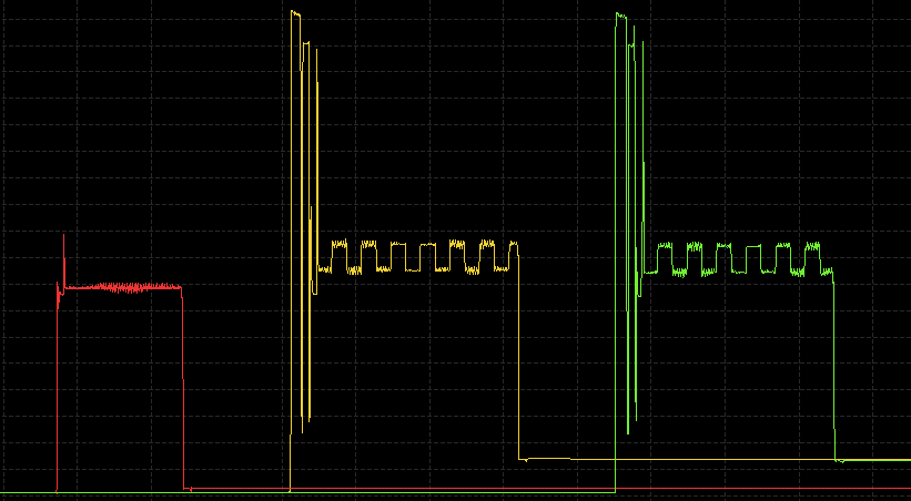
Finally, we have a test case that periodically gets measurements from two sensors: The Lis3dh accelerometer reports its orientation every second, the CCS811 reports the CO2 concentration every 10 seconds. After a measurement has come in, we can reasonably expect that no other work has to be done for a little while, so we enter System OFF mode. The system is configured to wake up again when a new measurement comes in.
This time, we only have two implementations: an interrupt-based synchronous solution, and an embassy async one.
| setup | avg. current draw (mA) |
|---|---|
| sync | 1.47 |
| async | 1.47 |
So in our case the performance is roughly the same. When zoomed in, the async version is ever so slightly faster than the sync one, but the difference is probably not significant.
Conclusion
We are encouraged by these results. We were perhaps too optimistic to expect a clear advantage for async in this case. Nonetheless, async is clearly competitive. The async mechanism is more fine-grained in its task switching than we could ever put up with if we had to write it all out ourselves.
The main downside, for now, is that async infects: when the lowest levels are async (in this case, UART or I2C) then layers above that, in particular communication with sensors, also needs to be asynchronous (or at least requires manual code changes). More about this tradeoff in a later post.
For now, we are extremely happy with the results and methodology, and look forward to applying this knowledge in future projects.
Update: we've published the code used to run the measurements here.
This is the 2nd article in a series on async embedded development with Rust:
- Async and asleep: designing our future embedded applications
- Measuring power consumption: sync vs. async
- Async on Embedded: Present & Future
Want to explore Embedded Rust?
We offer:
- introductory talks
- off-the-shelf or tailor-made workshops
- flexible team augmentation options